
Introduction
In today’s cloud-native world, building scalable, secure, and highly available applications is no longer optional, it’s essential. As applications grow in complexity and user demands increase, the architecture that supports them must be robust enough to handle failures, scale seamlessly, and maintain security boundaries between different components.
This is the first part of a two-part series where we’ll explore how to build a production-grade three-tier architecture on AWS using Terraform. In this article, we’ll focus on the theoretical foundations: what three-tier architecture is, why it matters, and how each component works together to create a resilient system.
What You’ll Learn
- The fundamental principles of three-tier architecture
- How AWS services work together to create separation of concerns
- Networking concepts: VPCs, subnets, route tables, and gateways
- Security best practices with Security Groups and Network ACLs
- High availability strategies with Multi-AZ deployments
- The role of load balancers and auto-scaling in production systems
By the end of this article, you’ll have a solid understanding of the architecture we’ll be implementing with Terraform in Part 2.
What is Three-Tier Architecture?
Three-tier architecture is a client-server software design pattern that divides an application into three distinct logical and physical layers, each with specific responsibilities:
1. Presentation Tier (Web Tier) – The user interface layer that handles client requests and presents information to users
2. Application Tier (Logic Tier) – The business logic layer that processes data, makes decisions, and coordinates between the presentation and data layers
3. Data Tier (Database Tier) – The data storage and retrieval layer that manages persistent data

*Figure 1: AWS three-tier architecture with public/private subnets across multiple availability zones*
This separation of concerns brings several architectural benefits:
- Independent Development: Each tier can be developed, tested, and deployed independently
- Scalability: Each layer can scale horizontally without affecting others
- Maintainability: Changes to one tier don’t require modifications to others
- Security: Physical and logical separation provides security boundaries
- Reusability: Business logic in the application tier can be shared across multiple presentation interfaces
Evolution from Monolithic Architecture
Traditional monolithic applications bundle the frontend, backend, and database logic in a single codebase running on one server. While simple to develop initially, this approach creates several problems:
- Single Point of Failure: If the server goes down, the entire application is unavailable
- Scaling Challenges: You must scale the entire application, even if only one component needs more resources
- Deployment Risks: Every change requires deploying the entire application
- Technology Lock-in: All components must use the same technology stack
Three-tier architecture addresses these issues by physically and logically separating concerns, allowing each tier to scale, fail, and be maintained independently.
Why Three-Tier Architecture?
Before diving into the implementation details, let’s understand why organizations choose three-tier architecture for their production workloads.
1. Scalability and Elasticity
Each tier can scale independently based on demand:
- Web tier can scale during traffic spikes (e.g., product launches, marketing campaigns)
- Application tier can scale when processing intensive operations
- Database tier can scale storage and read replicas independently
This granular scaling is cost-efficient, you only pay for resources each tier actually needs.
2. High Availability and Fault Tolerance
By deploying components across multiple Availability Zones (AZs), the architecture ensures:
- If one AZ fails, services continue in other AZs
- Load balancers automatically route traffic away from unhealthy instances
- Auto Scaling Groups replace failed instances automatically
- Database failover happens automatically with Multi-AZ deployments
3. Security Through Network Segmentation
Separating tiers into different subnets with specific security rules provides defense in depth:
- Web tier in public subnets accepts internet traffic but only on ports 80/443
- Application tier in private subnets accepts traffic only from the web tier
- Database tier in isolated private subnets accepts connections only from the application tier
- No direct internet access to backend tiers, attacks must breach multiple layers
4. Cost Optimization
Three-tier architecture enables cost optimization strategies:
- Use smaller, cost-effective instances for web tier (stateless workloads)
- Scale expensive database instances only when needed
- Auto Scaling reduces costs during low-traffic periods
- Spot instances can be used for non-critical tiers
5. Maintainability and Agility
Teams can work independently on different tiers:
- Frontend developers work on web tier without touching backend
- Backend developers modify APIs without affecting the database schema
- Database administrators optimize queries and schema independently
- CI/CD pipelines can deploy tiers separately with minimal downtime
High-Level Architecture Overview
Let’s look at the complete architecture we’ll be building. This diagram shows all major components and their relationships:
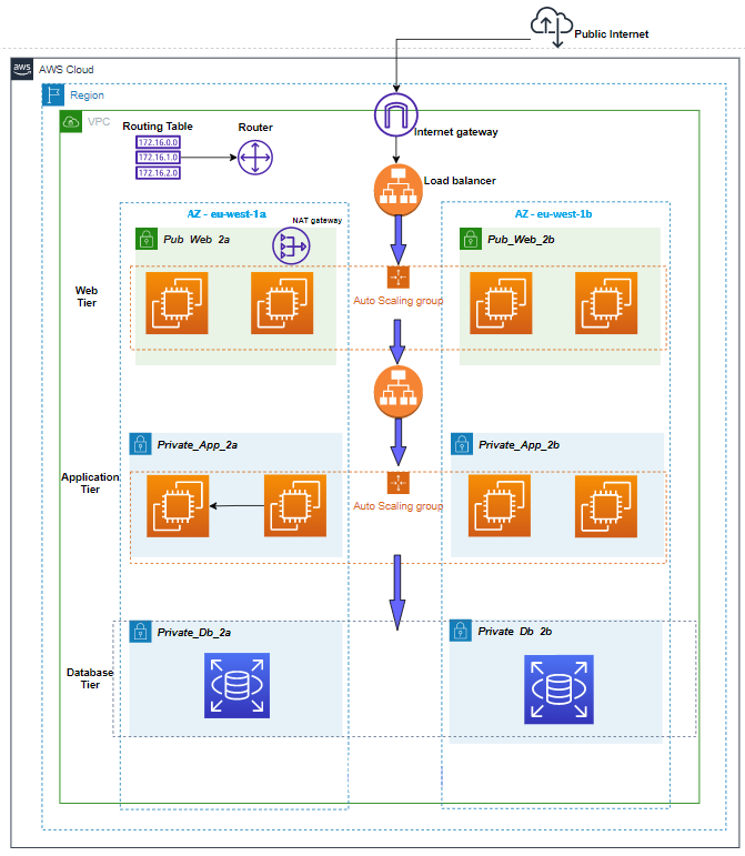
*Figure 2: Complete VPC architecture showing public/private subnets, NAT Gateway, and Auto Scaling Groups*
Architecture Components
Our three-tier architecture consists of the following AWS services:
- | Network Foundation | Isolated virtual network | VPC with CIDR block |
- | Public Subnets | Host internet-facing resources | 2 subnets across 2 AZs |
- | Private Subnets | Host backend resources | 4 subnets (2 for app, 2 for DB) across 2 AZs |
- | Internet Gateway | Enables internet access for public resources | Internet Gateway (IGW) |
- | NAT Gateway | Allows private resources to access internet | NAT Gateway in public subnet |
- | Load Balancer | Distributes traffic across web servers | Application Load Balancer (ALB) |
- | Web Servers | Serve frontend application | EC2 instances (Apache/Nginx/PHP) |
- | App Servers | Run business logic | EC2 instances (Node.js/Python/Java) |
- | Database | Store persistent data | RDS Multi-AZ (MySQL/PostgreSQL) |
- | Auto Scaling | Automatically adjust capacity | Auto Scaling Groups (ASGs)
- | Security | Control traffic flow | Security Groups & NACLs |
Key Design Decisions
1. Multi-AZ Deployment: All tiers span at least 2 Availability Zones for high availability
2. Private Subnets for Backend: Application and database tiers have no direct internet access
3. Load Balancer as Entry Point: All user traffic flows through ALB for distribution and SSL termination
4. Auto Scaling Groups: Both web and app tiers can scale horizontally based on demand
5. RDS Multi-AZ: Database has automatic failover to standby in different AZ
Foundation Layer: VPC and Networking
The Virtual Private Cloud (VPC) is the foundation of our architecture. It provides isolated network space where we deploy our resources with full control over IP addressing, routing, and security.
VPC Design
CIDR Block Planning
Our VPC uses a CIDR block that provides sufficient IP addresses while allowing for future expansion:
- VPC CIDR: 10.0.0.0/16
- Available IPs: 65,536 addresses
This large block allows us to create multiple subnets across multiple AZs without running out of IP space.
Subnet Strategy
We create 6 subnets across 2 Availability Zones for redundancy:
- | Public Subnet 1 | 10.0.1.0/24 | us-east-1a | Web tier (256 IPs) |
- | Public Subnet 2 | 10.0.2.0/24 | us-east-1b | Web tier (256 IPs) |
- | Private Subnet 1 (App) | 10.0.3.0/24 | us-east-1a | Application tier (256 IPs) |
- | Private Subnet 2 (App) | 10.0.4.0/24 | us-east-1b | Application tier (256 IPs) |
- | Private Subnet 3 (DB) | 10.0.5.0/24 | us-east-1a | Database tier (256 IPs) |
- | Private Subnet 4 (DB) | 10.0.6.0/24 | us-east-1b | Database tier (256 IPs) |
Important: AWS reserves 5 IP addresses in each subnet (network address, VPC router, DNS, future use, and broadcast), so each /24 subnet actually provides 251 usable IPs.
Internet Gateway (IGW)
The Internet Gateway enables communication between resources in public subnets and the internet:
How It Works:
- 1. Attached to the VPC (one IGW per VPC)
- 2. Allows bidirectional traffic: inbound from internet, outbound to internet
- 3. Performs Network Address Translation (NAT) for instances with public IPs
- 4. Highly available and horizontally scaled by AWS (no management needed)
- 5. No additional cost—you only pay for data transfer
Routing: Public subnets have a route table entry:
- Destination: 0.0.0.0/0 → Target: igw-xxxxx
This means “any traffic destined for the internet goes through the Internet Gateway.”
NAT Gateway
The NAT Gateway enables instances in private subnets to access the internet for updates, patches, and external API calls, while **eventing inbound connections from the internet:
Key Differences from Internet Gateway:
- | Direction | Bidirectional (in/out) | Outbound only |
- | Subnet Type | Public subnets | Used by private subnets |
- | Public IP | Resources need public IP | NAT Gateway has Elastic IP |
- | Quantity | One per VPC | One per AZ (for HA) |
- | Cost | No additional cost | Hourly charge + data transfer |
- | Management | Fully managed by AWS | Fully managed by AWS |
- | Bandwidth | No limit | 5 Gbps, scales to 100 Gbps |
How It Works:
- 1. Private instance initiates connection to the internet
- 2. Request goes through NAT Gateway in the public subnet
- 3. NAT Gateway uses its public Elastic IP as the source
- 4. NAT Gateway routes request to internet via Internet Gateway
- 5. Response returns to NAT Gateway
- 6. NAT Gateway forwards response to the original private instance
Routing: Private subnets have a route table entry:
- Destination: 0.0.0.0/0 → Target: nat-xxxxx
High Availability Best Practice: Deploy one NAT Gateway per Availability Zone. If you only deploy one NAT Gateway in AZ-A, then instances in AZ-B must route traffic cross-AZ, which increases latency and costs. If AZ-A fails, instances in AZ-B lose internet access.
Route Tables
Route tables control where network traffic is directed:[web:306]
Public Route Table (associated with public subnets):
- 10.0.0.0/16 → local (VPC internal traffic)
- 0.0.0.0/0 → igw-xxxxx (internet traffic)
Private Route Table (associated with private app/DB subnets):
- 10.0.0.0/16 → local (VPC internal traffic)
- 0.0.0.0/0 → nat-xxxxx (internet traffic via NAT)
Database Route Table (associated with DB subnets, more restrictive):
- 10.0.0.0/16 → local (VPC internal traffic only)
Some architectures remove internet access entirely from database subnets for maximum security.
Tier 1: Web/Presentation Tier
The web tier is the entry point for all user traffic. It serves the frontend application (HTML, CSS, JavaScript) and handles initial HTTP/HTTPS requests.
Application Load Balancer (ALB)
The Application Load Balancer sits in front of the web tier and distributes incoming traffic across multiple EC2 instances:
Key Features:
- Layer 7 Load Balancing: Operates at the HTTP/HTTPS level, can route based on URL paths, hostnames, headers
- Multi-AZ Deployment: Automatically distributes traffic across all enabled AZs
- Health Checks: Continuously monitors backend instances and removes unhealthy targets
- SSL/TLS Termination: Handles HTTPS encryption/decryption, reducing load on backend servers
- Connection Draining: Gracefully drains connections before removing instances
- Sticky Sessions: Can route users to the same instance based on cookies
How ALB Health Checks Work:
Health Check Configuration:
– Protocol: HTTP
– Path: /health or /
– Port: 80
– Interval: 30 seconds
– Timeout: 5 seconds
– Healthy threshold: 2 consecutive successes
– Unhealthy threshold: 3 consecutive failures
If an instance fails 3 consecutive health checks, ALB marks it unhealthy and stops sending traffic. If it passes 2 consecutive checks, it’s marked healthy again.
Target Groups: ALB routes traffic to target groups, which contain the EC2 instances:
ALB Listener (Port 80) → Target Group → EC2 Instances (Web Tier)
Web Tier EC2 Instances
Web tier runs on EC2 instances managed by an Auto Scaling Group:
Instance Configuration:
- OS: Amazon Linux 2023 or Ubuntu
- Software Stack: Apache/Nginx web server + PHP (or Node.js for static serving)
- Instance Type: t3.micro or t3.small (burstable performance for cost efficiency)
- Storage: 8-20 GB gp3 EBS volume
- Networking: Deployed in public subnets across 2 AZs
Application Responsibilities:
- Serve static assets (HTML, CSS, JavaScript, images)
- Handle user sessions
- Forward API requests to the application tier
- Render dynamic content from application tier responses
Auto Scaling Group (ASG) for Web Tier
The Auto Scaling Group ensures the web tier maintains desired capacity and automatically replaces failed instances:
Capacity Configuration:
Minimum Capacity: 2 instances (high availability across 2 AZs)
Desired Capacity: 2 instances (normal operation)
Maximum Capacity: 6 instances (scale during traffic spikes)
Scaling Policies:
Scale Out (add instances):
– Trigger: Average CPU utilization > 70% for 2 consecutive minutes
– Action: Add 1 instance
Scale In (remove instances):
– Trigger: Average CPU utilization < 30% for 5 consecutive minutes
– Action: Remove 1 instance
Health Checks:
ASG performs two types of health checks:
- EC2 Health Check: Is the instance running and responding?
- ELB Health Check: Is the instance passing ALB health checks?
If either check fails, ASG terminates the unhealthy instance and launches a replacement.
Launch Template: ASG uses a Launch Template that defines:
- AMI (Amazon Machine Image)
- Instance type
- Security group
- User data script (for automated software installation)
- SSH key pair for access
Tier 2: Application/Business Logic Tier
The application tier contains the business logic and processes all API requests from the web tier. This tier is isolated in private subnets with no direct internet access.
Application Tier EC2 Instances
Instance Configuration:
- OS: Amazon Linux 2023 or Ubuntu
- Software Stack: Node.js, Python (Django/Flask), Java (Spring Boot), or Go
- Instance Type: t3.small to t3.medium (more CPU/memory for processing)
- Storage: 20-50 GB gp3 EBS volume
- Networking: Deployed in private app subnets across 2 AZs
Application Responsibilities:
- Expose RESTful APIs or GraphQL endpoints
- Implement business logic (validation, calculations, workflows)
- Query and update database
- Handle authentication and authorization
- Process background jobs
- Call external APIs (via NAT Gateway)
Example API Structure:
GET /api/users – List all users
GET /api/users/:id – Get specific user
POST /api/users – Create new user
PUT /api/users/:id – Update user
DELETE /api/users/:id – Delete user
Internal Load Balancer (Optional)
For larger deployments, you can place an internal Application Load Balancer in front of the application tier:
Web Tier → Internal ALB → App Tier InstancesThis provides:
- Load distribution across multiple app servers
- Health checks for app instances
- Service discovery (web tier only needs to know ALB DNS)
- Decoupling between web and app tiers
For smaller deployments, the web tier can connect directly to app tier instances.
Auto Scaling Group for App Tier
Similar to the web tier, the application tier uses Auto Scaling:
- Minimum Capacity: 2 instances
- Desired Capacity: 2 instances
- Maximum Capacity: 8 instances
Scaling Policies (example):
- Scale out when average CPU > 60% for 3 minutes
- Scale in when average CPU < 25% for 5 minutes
Alternative scaling metrics:
- Request count per target (requests per second)
- Memory utilization (requires CloudWatch agent)
- Custom application metrics (queue depth, processing time)
Database Connection Management
Application tier connects to the database using:
- Connection pooling to reuse database connections efficiently
- RDS endpoint (single endpoint that automatically points to primary)
- Environment variables for connection strings (injected via user data or Parameter Store)
- IAM database authentication (optional, for enhanced security)
Example connection configuration:
const dbConfig = {
  host: process.env.DB_ENDPOINT,
  port: 3306,
  user: process.env.DB_USER,
  password: process.env.DB_PASSWORD,
  database: process.env.DB_NAME,
  connectionLimit: 10
};
Tier 3: Database/Data Tier
The database tier is the most critical component—it stores all persistent data. This tier is isolated in dedicated private subnets with the strictest security rules.
Amazon RDS Multi-AZ
Amazon RDS (Relational Database Service) provides managed database instances with automatic backups, patching, and Multi-AZ deployment for high availability:
Supported Engines:
- MySQL
- PostgreSQL
- MariaDB
- Oracle
- SQL Server
- Amazon Aurora (MySQL/PostgreSQL compatible)
Multi-AZ Deployment Architecture:
Primary DB Instance (AZ-A) ←→ Synchronous Replication ←→ Standby DB Instance (AZ-B)How Multi-AZ Works:
- Synchronous Replication: Every write to the primary is automatically replicated to the standby before the write is acknowledged to the application
- Automatic Failover: If the primary fails, RDS automatically promotes the standby to primary (typically 60-120 seconds)
- Single Endpoint: Application connects to a single DNS endpoint that automatically points to the current primary
- No Read Traffic to Standby: The standby is only for failover, not for read scaling
Failover Triggers:
- Loss of availability in primary AZ
- Loss of network connectivity to primary
- Compute unit failure on primary
- Storage failure on primary
- Manual failover initiated for testing
Multi-AZ with Two Readable Standbys (newer option):
For MySQL and PostgreSQL, AWS offers Multi-AZ DB Cluster with:
- 1 primary (read/write) in AZ-A
- 2 readable standbys (read-only) in AZ-B and AZ-C
- Faster failover (typically under 35 seconds)
- Read traffic can be offloaded to standbys
- 2x faster transaction commit latency
Database Subnet Group
RDS requires a DB Subnet Group that spans multiple AZs:
DB Subnet Group: “rds-subnet-group”
– Subnet 1: 10.0.5.0/24 (AZ-A)
– Subnet 2: 10.0.6.0/24 (AZ-B)
This allows RDS to place the primary and standby in different AZs automatically.
Backup and Recovery
RDS provides automated backup and point-in-time recovery:
Automated Backups:
- Daily automated snapshot during backup window
- Retention period: 1-35 days
- Transaction logs backed up every 5 minutes
- Point-in-time recovery to any second within retention period
Manual Snapshots:
- User-initiated snapshots
- Retained until explicitly deleted
- Can be copied across regions
- Used for long-term archival
Example Backup Configuration:
- Backup Window: 03:00-04:00 UTC (low traffic period)
- Retention Period: 7 days
- Multi-AZ: Enabled (backups taken from standby, no performance impact)
Performance Optimization
Instance Sizing:
Start with appropriate instance size based on workload:
- db.t3.micro: Development/testing (1 vCPU, 1 GB RAM)
- db.t3.small: Small production (2 vCPU, 2 GB RAM)
- db.m5.large: Medium production (2 vCPU, 8 GB RAM)
- db.r5.xlarge: Memory-intensive (4 vCPU, 32 GB RAM)
Storage:
- Use gp3 (General Purpose SSD) for most workloads
- Configure appropriate IOPS and throughput
- Enable storage autoscaling to prevent running out of space
Read Replicas (optional, separate from Multi-AZ):
For read-heavy workloads, create read replicas:
- Asynchronously replicated from primary
- Can be in same region or different region
- Application directs read queries to replicas
- Write queries still go to primary
Security Architecture
Security in three-tier architecture is implemented through defense in depth, multiple layers of security controls that work together.
Security Groups (Instance-Level Firewalls)
Security Groups are stateful firewalls that control traffic at the instance level:
Stateful Behavior: If you allow inbound traffic from a source, response traffic is automatically allowed outbound (and vice versa).
Web Tier Security Group (web-sg):
Inbound Rules:
- Port 80 (HTTP) from 0.0.0.0/0 (internet)
- Port 443 (HTTPS) from 0.0.0.0/0 (internet)
- Port 22 (SSH) from your-ip/32 (admin access)

Outbound Rules:
- All traffic to 0.0.0.0/0 (allow all outbound)
Application Tier Security Group (app-sg):
Inbound Rules:
- Port 3000 (API) from web-sg (only web tier can access)
- Port 22 (SSH) from bastion-sg (admin access via bastion)

Outbound Rules:
- Port 3306 (MySQL) to db-sg (database access)
- Port 443 (HTTPS) to 0.0.0.0/0 (external API calls
Database Security Group (db-sg):
Inbound Rules:
- Port 3306 (MySQL) from app-sg (only app tier can access)

Outbound Rules:
- None required (database doesn't initiate outbound connections)
Key Security Principle: Each tier only accepts traffic from the tier directly above it.
Internet → Web Tier (Port 80/443)
Web Tier → App Tier (Port 3000)
App Tier → DB Tier (Port 3306)
This creates a trust boundary at each layer. An attacker who compromises the web tier cannot directly access the database, they must also compromise the application tier.
Network ACLs (Subnet-Level Firewalls)
Network ACLs (NACLs) provide an additional layer of security at the subnet level:
Stateless Behavior: Unlike Security Groups, NACLs are stateless—you must explicitly allow both inbound and outbound traffic.
Public Subnet NACL:
Inbound Rules:
100 - Allow HTTP (80) from 0.0.0.0/0
110 - Allow HTTPS (443) from 0.0.0.0/0
120 - Allow SSH (22) from your-ip/32
130 - Allow ephemeral ports (1024-65535) from 0.0.0.0/0
*   - Deny all

Outbound Rules:
100 - Allow all traffic to 0.0.0.0/0
*   - Deny all
Private Subnet NACL
Inbound Rules:
100 - Allow traffic from 10.0.0.0/16 (VPC internal)
*   - Deny all

Outbound Rules:
100 - Allow traffic to 10.0.0.0/16 (VPC internal)
110 - Allow HTTPS (443) to 0.0.0.0/0 (for updates)
*   - Deny all
Security Groups vs NACLs:
| Feature | Security Groups | Network ACLs |
- | Level | Instance | Subnet |
- | State | Stateful | Stateless |
- | Rules | Allow rules only | Allow and deny rules |
- | Processing | All rules evaluated | Rules evaluated in order |
- | Association | Attached to ENI | Attached to subnet |
- | Best Use | Primary security control | Additional layer (optional) |
Best Practice: Use Security Groups as the primary security mechanism. NACLs are typically left at default (allow all) unless you need explicit deny rules or subnet-level controls.
IAM Roles for EC2 Instances
Instead of storing AWS credentials on EC2 instances, use IAM Roles:
Web Tier Role (example permissions):
{

  "Effect": "Allow",
  "Action": [
    "s3:GetObject",
    "s3:PutObject"
  ],
  "Resource": "arn:aws:s3:::my-static-assets/*"
}App Tier Role (example permissions):
{

  "Effect": "Allow",
  "Action": [
    "rds:DescribeDBInstances",
    "secretsmanager:GetSecretValue",
    "ssm:GetParameter"
  ],
  "Resource": "*"
}Benefits:
- No hardcoded credentials in code
- Automatic credential rotation
- Fine-grained permissions per tier
- Audit trail via CloudTrail
Data Encryption
Encryption in Transit:
- Use HTTPS/TLS for all web traffic (ALB handles SSL termination)
- Use SSL/TLS for database connections
- Use HTTPS for external API calls
Encryption at Rest:
- Enable EBS encryption for EC2 volumes
- Enable RDS encryption for database storage
- Use AWS KMS (Key Management Service) for key management
Traffic Flow Through the Architecture
Let’s trace a complete user request through our three-tier architecture:
Step-by-Step Request Flow
Step 1: User Request
User's Browser → HTTPS Request → Route 53 (DNS) → ALB Public IPUser enters `https://myapp.example.com` in their browser. DNS resolves to the Application Load Balancer’s public IP address.
Step 2: Load Balancer Distribution
ALB → Health Check → Target Group → Select Healthy Instance (Web Tier)ALB receives the request and selects a healthy web tier instance based on:
- Health check status
- Connection count (least connections algorithm)
- Availability zone distribution
Step 3: Web Tier Processing
Web Tier EC2 (10.0.1.50) → Serve Static HTML/CSS/JS → BrowserWeb server (Apache/Nginx) serves the frontend application. Browser loads JavaScript that will make API calls.
Step 4: API Request to Application Tier
Browser → JavaScript Fetch → ALB → Web Tier → App Tier (10.0.3.20:3000)JavaScript makes an API request (e.g., `GET /api/users`):
- Request goes through ALB to web tier
- Web tier forwards to application tier internal IP
- Application tier receives request on port 3000
Step 5: Database Query
App Tier → SQL Query → RDS Endpoint (mydb.abc123.us-east-1.rds.amazonaws.com:3306)Application tier:
- Validates request
- Constructs SQL query: `SELECT * FROM users WHERE active = 1`
- Connects to RDS primary instance via endpoint
- Executes query
Step 6: Response Back Through Layers
Database → App Tier → Web Tier → ALB → User's BrowserResponse flows back through each layer:
- RDS returns query results to app tier
- App tier processes data, formats JSON response
- App tier sends JSON to web tier
- Web tier returns response to ALB
- ALB returns response to user’s browser
- JavaScript renders data on the page
High Availability and Fault Tolerance
High availability (HA) means the system remains operational even when components fail. Our architecture achieves HA through redundancy at every layer:
Multi-AZ Deployment Strategy
Every tier is deployed across at least 2 Availability Zones:
Availability Zones are physically separate data centers within a region, each with independent power, networking, and cooling. They are connected via low-latency links.
Why Multiple AZs Matter:
- AZ failure rate: ~0.1% per year (extremely rare, but happens)
- By deploying across 2 AZs, you achieve 99.99%+ availability
- Natural disasters, power outages, or network issues affecting one AZ don’t impact the other
Failure Scenarios and Recovery
Let’s examine how the architecture handles different failure scenarios:
Scenario 1: Web Tier Instance Failure
Instance fails → ALB health check detects failure (30 seconds) →
ALB stops routing traffic → ASG detects unhealthy instance →
ASG terminates failed instance and launches replacement (2-3 minutesImpact: None. ALB immediately routes traffic to healthy instances in the target group.
Scenario 2: Application Tier Instance Failure
Instance fails → Web tier requests fail → ASG health check fails → ASG replaces instance → New instance joins and starts processingImpact: Minimal. Requests may fail during detection period (30-60 seconds), but retries succeed.
Scenario 3: Database Primary Failure
Primary DB fails → RDS detects failure (60 seconds) → RDS promotes standby to primary (60 seconds) → RDS updates DNS endpoint to point to new primary → Application tier reconnects automaticallyImpact: Database unavailable for 1-2 minutes. Application tier connections fail, but retry logic reconnects to new primary.[web:317][web:321]
Scenario 4: Entire Availability Zone Failure
AZ-A fails → ALB stops routing to AZ-A instances → All traffic routes to AZ-B instances → ASGs launch replacement instances in AZ-B → Database failover (if primary was in AZ-A)Impact: Brief degradation (1-2 minutes) while traffic shifts and failover completes. System remains operational on AZ-B.
Why Terraform for Infrastructure as Code?
Now that we understand the architecture, let’s discuss why we use Terraform to deploy it rather than manually clicking in the AWS Console.
Infrastructure as Code (IaC) Benefits
1. Repeatability and Consistency
With Terraform, you define your infrastructure once and deploy it consistently across environments:
- Development → Staging → Production
Every environment gets the exact same configuration. No “works in dev but not in prod” issues caused by manual differences.
2. Version Control
Your infrastructure becomes code that lives in Git:
- Track every change with commit messages
- Review infrastructure changes via pull requests
- Roll back to previous versions if something breaks
- Collaborate with team members effectively
3. Automation and Speed
Manual deployment of three-tier architecture takes hours and is error-prone. Terraform deploys the entire infrastructure in 10-15 minutes:
terraform init    # Initialize providers

terraform plan    # Preview changes

terraform apply # Deploy infrastructure4. Documentation
Terraform configuration files serve as documentation:
resource "aws_instance" "web" {

  ami           = "ami-0c55b159cbfafe1f0"
  instance_type = "t3.micro"
  subnet_id     = aws_subnet.public[0].id
  tags = {
    Name = "web-server"
    Tier = "web"
  }
}Anyone reading the code understands what resources exist and how they’re configured.
5. State Management
Terraform maintains a state file that tracks:
- What resources exist
- Current configuration
- Dependencies between resources
- Drift detection (manual changes in AWS console)
This allows Terraform to know what needs to be created, updated, or destroyed.
Terraform Modules for Three-Tier Architecture
Our implementation uses modules to organize infrastructure:
terraform-three-tier/
├── main.tf
├── variables.tf
├── outputs.tf
└── modules/
    ├── networking/
    │   ├── main.tf       (VPC, subnets, IGW, NAT)
    │   ├── variables.tf
    │   └── outputs.tf
    ├── security/
    │   ├── main.tf       (Security groups)
    │   ├── variables.tf
    │   └── outputs.tf
    ├── compute/
    │   ├── main.tf       (ASG, Launch Templates, ALB)
    │   ├── variables.tf
    │   └── outputs.tf
    └── database/
        ├── main.tf       (RDS instance)
        ├── variables.tf
└── outputs.tfBenefits of Modules:
- Reusability: Use the same networking module across projects
- Maintainability: Update one module, all projects benefit
- Testing: Test modules independently
- Encapsulation: Hide complexity behind clean interfaces
Conclusion
In this first part of our series, we’ve covered the theoretical foundations of building a scalable three-tier architecture on AWS:
Key Takeaways
1. Three-tier architecture separates concerns into presentation, application, and data layers, enabling independent scaling, security, and development
2. VPC networking provides the foundation with public subnets for internet-facing resources and private subnets for backend components
3. Application Load Balancer distributes traffic across multiple web servers and performs health checks to ensure high availability
4. Auto Scaling Groups automatically maintain capacity, replace failed instances, and scale based on demand
5. RDS Multi-AZ provides automatic database failover with synchronous replication across availability zones
6. Security is layered: Security Groups, Network ACLs, IAM roles, and encryption work together to create defense in depth
7. High availability is achieved through multi-AZ deployment, redundant components, and automatic failover mechanisms
8. Terraform enables infrastructure as code, providing repeatability, version control, and automation
What’s Next?
In Part 2, we’ll implement this entire architecture using Terraform:
- Writing Terraform modules for networking, security, compute, and database
- Configuring user data scripts for automated EC2 setup
- Setting up Auto Scaling policies and health checks
- Deploying the complete infrastructure with `terraform apply`
- Testing high availability and failover scenarios
- Troubleshooting common issues and best practices
By combining the theoretical knowledge from this article with the hands-on implementation in Part 2, you’ll have a complete understanding of production-grade AWS architecture.
References
- AWS Architecture Blog. (2024). Building a three-tier architecture on a budget. https://aws.amazon.com/blogs/architecture/building-a-three-tier-architecture-on-a-budget/
- GeeksforGeeks. (2024). How to integrate AWS auto scaling with application load balancer. https://www.geeksforgeeks.org/devops/how-to-integrate-aws-auto-scaling-with-application-load-balancer/
- Subnet Calculator. (2025). AWS VPC subnetting best practices: Reserved IPs and CIDR planning. https://www.subnetcalculator.dev/blog/aws-vpc-subnetting-best-practices
- AWS. (2026). Amazon RDS Multi-AZ deployments. https://aws.amazon.com/rds/features/multi-az/
- AWS Documentation. Amazon RDS Multi-AZ deployment configuration. https://docs.aws.amazon.com/AmazonRDS/latest/UserGuide/Concepts.MultiAZ.html
- AWS Blog. (2010). Building three-tier architectures with security groups. https://aws.amazon.com/blogs/aws/building-three-tier-architectures-with-security-groups/
*Stay tuned for Part 2, where we’ll dive into the Terraform code and deploy this entire architecture from scratch!*
Leave a Reply